- Introduction to FDM: Frequency-Division Multiplexing (FDM) is a technique used in telecommunications to transmit multiple signals simultaneously over a single communication channel. It is based on the principle of dividing the available frequency spectrum into multiple non-overlapping frequency bands, each dedicated to a different signal.
- Basic Principle: The fundamental principle of FDM is to allocate separate frequency bands to different signals for simultaneous transmission. Each signal occupies a specific frequency band within the overall frequency spectrum, and these bands are carefully spaced to prevent interference between signals.
- Frequency Spectrum Division: FDM divides the available frequency spectrum into smaller sub-bands, with each sub-band assigned to a different signal. The width of each sub-band corresponds to the bandwidth required to transmit the individual signal. The total width of all sub-bands combined should not exceed the bandwidth of the communication channel.
- Multiplexing Process: The process of multiplexing involves combining multiple signals into a composite signal that can be transmitted over the channel. In the case of FDM, the individual signals are modulated onto different carrier frequencies within their allocated frequency bands. These modulated signals are then combined to form a composite signal for transmission.
- Signal Modulation: Before combining the signals, each signal undergoes modulation, where the baseband signal is shifted to a higher frequency range to occupy its assigned frequency band. Common modulation techniques used in FDM include amplitude modulation (AM), frequency modulation (FM), or phase modulation (PM), depending on the specific application and signal characteristics.
- Bandwidth Requirements: Each signal in an FDM system requires a specific bandwidth to transmit its information effectively. The bandwidth depends on the nature of the signal, such as its data rate or frequency range. By allocating separate frequency bands, FDM ensures that each signal has the necessary bandwidth for its transmission.
- Interference Avoidance: To prevent interference between signals, the frequency bands allocated to different signals must be non-overlapping and carefully spaced. The spacing between adjacent frequency bands is known as guard bands or guard frequencies. These guard bands act as a buffer zone to minimize the risk of signal overlap and interference.
- Channel Capacity: The channel capacity of an FDM system depends on the total bandwidth of the communication channel and the width of each individual frequency band. The total bandwidth sets an upper limit on the number of signals that can be multiplexed simultaneously. The width of each frequency band determines the data rate or bandwidth allocated to each signal.
- Demultiplexing Process: At the receiving end, the composite signal carrying multiple signals is demultiplexed to separate the individual signals. This process is known as demultiplexing or demodulation. Demodulation involves extracting the original baseband signal from its respective carrier frequency.
- Advantages of FDM:
- Simultaneous Transmission: FDM enables multiple signals to be transmitted simultaneously over a single channel, thereby increasing the efficiency and capacity of the communication system.
- Compatibility: FDM is compatible with various modulation techniques, making it adaptable to different types of signals and systems.
- Flexibility: FDM allows for the easy addition or removal of signals within the frequency spectrum, providing flexibility in managing and expanding communication systems.
- Interference Isolation: By allocating non-overlapping frequency bands to different signals, FDM helps isolate signals and reduce the potential for interference between them.
- Limitations of FDM:
- Inefficient Use of Spectrum: FDM dedicates specific frequency bands to each signal, which may result in some portions of the spectrum being unused or underutilized if not all frequency bands are occupied.
- Frequency Synchronization: In an FDM system, the carrier frequencies of the modulated signals must be accurately synchronized at the transmitter and receiver to ensure proper demodulation. Any deviation in frequency synchronization can lead to signal distortion and degradation.
- Signal Crosstalk: Although FDM aims to prevent interference between signals, there is still a possibility of crosstalk between adjacent frequency bands. Crosstalk can occur due to imperfect filtering or insufficient guard band spacing.
- Applications of FDM:
- Analog Broadcast: FDM is commonly used in analog broadcasting systems, such as radio and television, where multiple audio or video signals are transmitted simultaneously over different frequency bands.
- Cable Television: FDM is employed in cable television (CATV) systems to deliver multiple television channels over a single coaxial cable by allocating specific frequency bands to each channel.
- Broadband Internet: FDM is utilized in broadband communication systems, such as Digital Subscriber Line (DSL) or cable internet, where different data channels are multiplexed over the same physical medium.
- Satellite Communication: FDM is employed in satellite communication systems to transmit multiple signals, such as voice, data, or video, over different frequency bands within the satellite’s allocated spectrum.
In summary, Frequency-Division Multiplexing (FDM) is a technique that enables the transmission of multiple signals over a single communication channel by dividing the frequency spectrum into non-overlapping bands. It allows for simultaneous transmission, efficient spectrum utilization, and compatibility with various modulation techniques. FDM has found applications in analog broadcast, cable television, broadband internet, and satellite communication systems. While FDM offers advantages such as flexibility and interference isolation, it also has limitations related to spectrum efficiency and frequency synchronization.
Frequency Division Multiplexing (FDM) System
The operation of frequency division multiplexing (FDM) is based on sharing the available bandwidth of a communication channel among the signals to be transmitted .
The modulated signals are then added together to form a composite signal which is transmitted over a single channel .
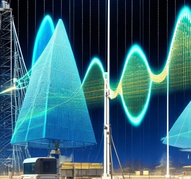
The spectrum of composite FDM signal has been shown in fig.1 .

FDM Transmitter
Fig.2 shows the block diagram of an FDM transmitter .

Fig. 2 : FDM Transmitter
The signals which are to be multiplexed will each modulate a separate carrier .The type of modulation can be AM, SSB, FM or PM .
The modulated signals are then added together to form a complex signal which is transmitted over a single channel .
Each signal modulates a separate carrier . The modulator outputs will contain the sidebands of the corresponding signals .
The modulator outputs are added together in a linear mixer or adder .
The linear mixer is different from the normal mixers. Here the sum and difference frequency components are not produced . But only the algebraic addition of the modulated outputs will take place .
Different signals are thus added together i the time domain but they have a separate identity in the frequency domain . This is as shown in fig.2 .
The composite signal at the output of mixer is transmitted over the single communication channel as shown in fig.2 . This signal can be used to modulate a radio transmitter if the FDM signal is to be transmitted through air .
FDM Receiver
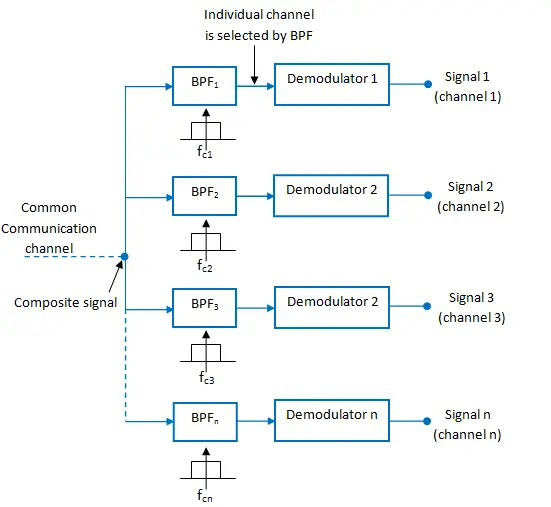
The block diagram of an FDM receiver is shown in fig.3 .
Fig.3 : FDM Receiver
The composite signal is applied to a group of bandpass filters (BPF) .
Each BPF has a center frequency corresponding to one of the carriers. The BPFs have an adequate bandwidth to pass all the channel information without any distortion .
Each filter will pass only its channel and rejects all the other channels .
The channel demodulator then removes the carrier and recovers the original signal back .